


2000m OTDR Launch Cable Box – Dead Zone Eliminator for Accurate Near-End Fiber Testing | G652D | SC / FC / LC / ST | UPC & APC
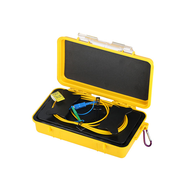
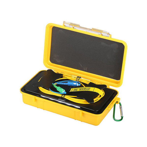
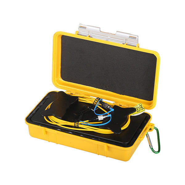
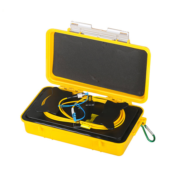
The 2000m OTDR Launch Cable Box is a field-ready fiber optic launch cable assembly containing 2,000 meters of G652D singlemode fiber wound inside a ruggedized, IP-rated hard-shell case. It connects between the OTDR and the fiber link under test to eliminate the OTDR’s near-end dead zone, enabling accurate measurement of insertion loss and reflectance at the first connector of the link — measurements that would otherwise be masked by the OTDR’s launch pulse recovery time.
Available with SC, FC, LC, and ST connectors in both UPC and APC polish, the 2000m launch cable box is the standard tool for OTDR testing of long-haul singlemode fiber links, FTTH feeder cables, and telecom OSP fiber where the near-end connector loss and reflectance must be accurately characterized.
What Is an OTDR Launch Cable Box and Why Is 2000m Needed?
Every OTDR has a dead zone at the beginning of a trace — a blind region caused by the recovery time of the OTDR’s receiver after the high-power launch pulse. During this dead zone, the OTDR cannot accurately measure events (connectors, splices, faults) on the fiber. The dead zone has two components:
- Event Dead Zone (EDZ): The minimum distance after a reflective event (such as a connector) before the OTDR can detect another event — typically 1–5 meters for modern OTDRs
- Attenuation Dead Zone (ADZ): The minimum distance after a reflective event before the OTDR can accurately measure loss — typically 10–80 meters depending on OTDR model and pulse width setting
By inserting a 2000m launch cable between the OTDR and the link under test, the OTDR’s dead zone is pushed 2,000 meters into the launch cable — well before the first connector of the actual link. A 2000m launch cable is recommended for OTDRs with longer pulse widths (used for long-haul testing) where the attenuation dead zone can extend to several hundred meters.
Key Features
- 2,000m G652D Singlemode Fiber: ITU-T G652.D compliant singlemode fiber — low attenuation (<0.5dB total at 1310nm for 2000m) ensures the launch cable itself does not significantly reduce OTDR dynamic range
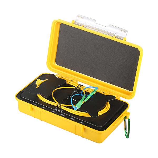
- Ruggedized Hard-Shell Case: SR Polypropylene case with compound latch and locking feature — protects the fiber from damage in field environments. Water and dust resistant for indoor and outdoor use
- Robust Carabiner Clip: Allows the launch box to be clipped to a belt, ladder, or equipment rack during testing — keeping both hands free
- Built-In Cable Management: Fiber is neatly wound inside the case with built-in cable management — no tangling or kinking during deployment and retrieval
- Auto-Purge Valve: Prevents pressure buildup inside the sealed case during temperature changes — maintains case integrity in outdoor environments
- SC / FC / LC / ST Connectors, UPC & APC: Available in the most common singlemode connector types and polish types — select the configuration that matches your OTDR port and the fiber link under test
- 2-Meter Lead Cables: 3mm buffer lead cables on both ends provide strain relief and easy connection to the OTDR port and the fiber link under test
Fiber & Connector Specifications
| Parameter | Specification |
|---|---|
| Fiber Type | G652D (ITU-T G652.D singlemode) |
| Fiber Length | 2,000m |
| Lead Length | 2 meters, 3mm buffer |
| Typical Loss | <0.5dB @ 1310nm (2000m total) |
| Connector Types | SC, FC, LC, ST |
| Polish Types | UPC, APC, PC |
| Return Loss (UPC) | ≥50dB |
| Return Loss (APC) | ≥60dB |
| Return Loss (PC) | ≥35dB |
| Repeatability | ≤0.2dB (1,000 mating cycles) |
| Exchangeability | ≤0.2dB |
Mechanical & Environmental Specifications
| Parameter | Specification |
|---|---|
| Case Dimensions | 238mm × 141mm × 67mm |
| Case Material | SR Polypropylene |
| Case Color | Yellow |
| Weight (without fiber) | 0.75kg |
| Operating Temperature | -40°C to +85°C |
| Storage Temperature | -40°C to +85°C |
| Humidity | 0 to 95%, non-condensing |
Compliance Standards
- ITU-T G652.D (singlemode fiber)
- ITU-T G656.A
- ITU-T G651.1 OM1, OM2, OM3, OM4
- IEC 60793-2-10 Type A1a.1/A1b (OM1/OM2), Type A1a.2 (OM3), Type A1a.3 (OM4)
- RoHS Compliant — Directive 2011/65/EU
How to Use the OTDR Launch Cable Box
- Select the correct connector configuration — match the launch cable’s connector type (SC/FC/LC/ST) and polish (UPC/APC) to your OTDR’s optical port and the fiber link under test
- Clean the connectors — inspect and clean both the OTDR port and the launch cable connectors before connecting. Contaminated connectors are the most common cause of poor OTDR traces
- Connect the launch cable to the OTDR — plug one end of the launch cable into the OTDR’s optical port
- Connect the launch cable to the fiber under test — plug the other end of the launch cable into the first connector of the fiber link under test
- Set the OTDR range and pulse width — set the OTDR range to cover the full length of the fiber link plus the 2000m launch cable. The OTDR trace will show the launch cable as the first 2000m of fiber before the link under test begins
- Acquire the OTDR trace — the near-end connector of the link under test will now appear clearly in the OTDR trace, outside the dead zone, with accurate loss and reflectance measurements
2000m vs. 500m vs. 1000m Launch Cable: Which Length Do You Need?
| Launch Cable Length | Recommended Use Case | Dead Zone Coverage |
|---|---|---|
| 500m | Short-range testing, OTDRs with short pulse widths, FTTH drop fiber testing | Covers EDZ and ADZ for most modern OTDRs at short pulse widths |
| 1000m | Medium-range testing, standard FTTH feeder and distribution fiber testing | Covers ADZ for most OTDRs at medium pulse widths |
| 2000m (this listing) | Long-haul testing, OTDRs with long pulse widths, applications requiring accurate near-end connector characterization | Covers ADZ for all OTDRs including those with long pulse widths (>1µs) |
We also stock 500m and 1000m OTDR launch cable boxes in the same connector configurations — see our related listings.
Ideal Applications
- Long-haul singlemode fiber testing — OTDR characterization of trunk fiber, feeder cables, and backbone fiber where long pulse widths create extended dead zones requiring a 2000m launch cable
- FTTH feeder fiber testing — accurate measurement of near-end connector loss at the OLT or splitter input on FTTH feeder cables
- Telecom OSP fiber acceptance testing — IEC/ITU-compliant OTDR testing of newly installed outside plant fiber cables, including accurate near-end connector characterization
- Fiber fault location — locating breaks, high-loss splices, and connector faults near the launch end of a fiber link that would otherwise be hidden in the OTDR dead zone
- Bidirectional OTDR testing — used as both a launch cable (from one end) and a receive cable (from the other end) for bidirectional OTDR measurements required by IEC 61280-4-1 and TIA-568 fiber acceptance standards
Frequently Asked Questions
Q: What is an OTDR launch cable box?
A: An OTDR launch cable box is a fiber optic cable assembly — typically 500m to 2000m of singlemode fiber wound in a protective case — that is connected between the OTDR and the fiber link under test. It pushes the OTDR’s dead zone away from the beginning of the link, allowing accurate measurement of the near-end connector and events close to the launch end of the fiber.
Q: Why do I need a 2000m launch cable instead of 500m or 1000m?
A: The required launch cable length depends on your OTDR’s attenuation dead zone (ADZ) at the pulse width you are using. For long-haul testing with long pulse widths (>1µs), the ADZ can extend to several hundred meters — a 2000m launch cable ensures the dead zone is fully contained within the launch cable for all OTDR models and pulse width settings.
Q: What connector type and polish should I choose?
A: Choose the connector type (SC, FC, LC, or ST) that matches your OTDR’s optical port and the fiber link under test. Choose APC (green connector, 8° angled) if your OTDR port or fiber link uses APC connectors — common in FTTH and PON networks. Choose UPC (blue connector) for standard telecom and enterprise fiber applications. APC and UPC connectors are not interchangeable.
Q: Can I use this launch cable box as a receive cable?
A: Yes. The launch cable box can be used as both a launch cable (connected at the near end of the OTDR) and a receive cable (connected at the far end of the fiber link) for bidirectional OTDR testing. Bidirectional testing is required by IEC 61280-4-1 and TIA-568 for fiber acceptance testing.
Q: What fiber type is used in this launch cable box?
A: The launch cable uses ITU-T G652.D singlemode fiber — the standard singlemode fiber type for FTTH, telecom OSP, and long-haul applications. It is compatible with all standard singlemode OTDRs operating at 1310nm and 1550nm.
Q: Is the case waterproof?
A: The case is water and dust resistant, rated for indoor and outdoor use across a wide temperature range (-40°C to +85°C). It features an auto-purge valve to prevent pressure buildup during temperature changes.
Q: For support or bulk orders?
A: Contact us at sales@opticfibertool.com for B2B pricing, volume orders, or technical support.
Package Contents
- 2000m OTDR Launch Cable Box (G652D fiber, selected connector type and polish) ×1